Difference between revisions of "Rock/wiringX"
| Line 22: | Line 22: | ||
== Pin Number Defined in WiringX== | == Pin Number Defined in WiringX== | ||
You can find pin numbers for Radxa Rock(pro/lite) [http://radxa.com/Rock/extension_header here]. However, only pins can be used as GPIO are valid in wiringX. Thus, for J8, totally 21 pins can be used (number defined as 0-20) and for J12/15, 8 pins can be used (number 25-32). Besides, 3 onboard LEDs can be used, (number 33-35). Pin number defined in wiringX is as below: | You can find pin numbers for Radxa Rock(pro/lite) [http://radxa.com/Rock/extension_header here]. However, only pins can be used as GPIO are valid in wiringX. Thus, for J8, totally 21 pins can be used (number defined as 0-20) and for J12/15, 8 pins can be used (number 25-32). Besides, 3 onboard LEDs can be used, (number 33-35). Pin number defined in wiringX is as below: | ||
| + | |||
[[File:pin-wiringX.png]] | [[File:pin-wiringX.png]] | ||
| + | |||
== GPIO == | == GPIO == | ||
| − | WiringX | + | WiringX provides digitalread and digitalwrite, after you set it as input/output using pinMode. The example below shows how to blink the blue LED (pin NO. 35) on board. |
''' #include <stdio.h>''' | ''' #include <stdio.h>''' | ||
'''#include <stdlib.h>''' | '''#include <stdlib.h>''' | ||
| Line 43: | Line 45: | ||
== I2C == | == I2C == | ||
To test I2C, SPI and ISR, an arduino uno is used. It has I2C and SPI, and can act as interrupt source. | To test I2C, SPI and ISR, an arduino uno is used. It has I2C and SPI, and can act as interrupt source. | ||
| + | |||
[[File:Arduino.png]] | [[File:Arduino.png]] | ||
| + | |||
I2C0 is connected to pin 31, 32 on J8. Code on radxa: | I2C0 is connected to pin 31, 32 on J8. Code on radxa: | ||
'''#include <stdio.h>''' | '''#include <stdio.h>''' | ||
| Line 141: | Line 145: | ||
''' } ''' | ''' } ''' | ||
'''}''' | '''}''' | ||
| − | |||
| − | |||
== ISR == | == ISR == | ||
Revision as of 13:11, 9 June 2015
Contents
WiringX is a modular approach to several GPIO interfaces. Till now, it supports five platforms: Raspberry Pi, Hummingboard, BananaPi, Radxa Rock and MIPS CI20 Creator. For Radxa Rock(pro/lite), wiringX provides interfaces for GPIO, I2C, SPI and ISR. You can easily use these function on Rock through wiringX.
Firstly, get wiringX from github:
   git clone https://github.com/wiringX/wiringX.git
   cd wiringX
or
   wget https://github.com/wiringX/wiringX/archive/master.zip
   unzip master.zip
   cd  wiringX-master
Then, install wiringX follow the way on github.
When compile your source code, add the static lib like:
   gcc -o test test.c /usr/local/lib/libwiringX.a
   ./test
WiringX is running on your board!
Pin Number Defined in WiringX
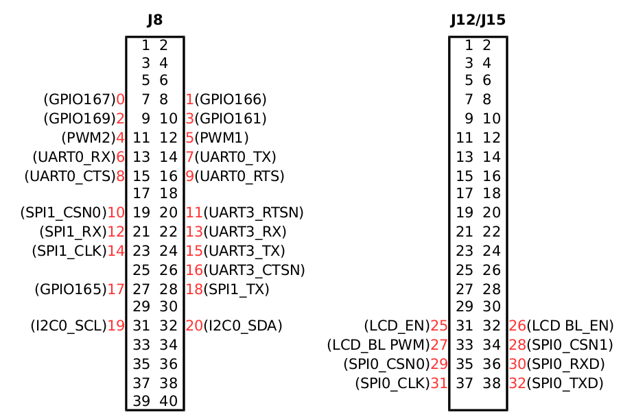
You can find pin numbers for Radxa Rock(pro/lite) here. However, only pins can be used as GPIO are valid in wiringX. Thus, for J8, totally 21 pins can be used (number defined as 0-20) and for J12/15, 8 pins can be used (number 25-32). Besides, 3 onboard LEDs can be used, (number 33-35). Pin number defined in wiringX is as below:
GPIO
WiringX provides digitalread and digitalwrite, after you set it as input/output using pinMode. The example below shows how to blink the blue LED (pin NO. 35) on board.
   #include <stdio.h>
   #include <stdlib.h>
   #include <unistd.h>
   #include "wiringX.h"
   int main(void) {
   	wiringXSetup();
   	pinMode(pinToGPIO[35], OUTPUT);
   	digitalWrite(pinToGPIO[35], HIGH);
   	sleep(1);
   	digitalWrite(pinToGPIO[35], LOW);
   	sleep(1);
   }
Theoretically, all pins can be used as GPIO. However, some multiplexed pins can't be used (pin number defined in extension header): J8: 11-16, 20, 22, 24, 26-28, 31-32; J12/15: 33-38. These pins can only be used as PWM, UART or SPI, not for GPIO.
I2C
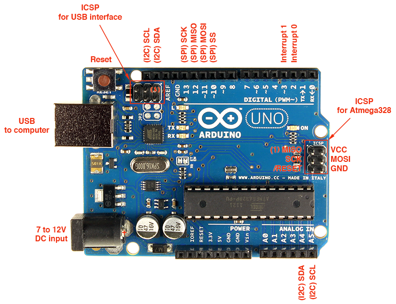
To test I2C, SPI and ISR, an arduino uno is used. It has I2C and SPI, and can act as interrupt source.
I2C0 is connected to pin 31, 32 on J8. Code on radxa:
   #include <stdio.h>
   #include <stdlib.h>
   #include <unistd.h>
   #include <stdint.h>
   #include "wiringX.h"
   #define I2C_ADDR        0x04
   int fd_i2c;
   int main(void) {
           wiringXSetup();
           if((fd_i2c = wiringXI2CSetup(I2C_ADDR)) < 0) {
                   fprintf(stderr, "I2C Setup failed: %i\n", fd_i2c);
                   return -1;
           } else {
                   fprintf(stderr, "I2C Setup OK: %i\n", fd_i2c);
           }
           int data=0;
           while(1) {
                   data=wiringXI2CRead(fd_i2c);
                   sleep(2);
                   printf("Data received is:%d\n",data);
           }
   }
Code on arduino:
    #include <Wire.h>
    byte i=0;
    void setup()
    {
      Wire.begin(4);
      Wire.onRequest(requestEvent);
    }
    void loop()
    {
      delay(100);
    }
    void requestEvent()
    {
      Wire.write(i);
      i++;
    }
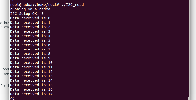
The result:
SPI
SPI0 and SPI1 are connected to J12/15, J8 respectively. A simple example on radxa:
   #include <stdio.h>
   #include <stdlib.h>
   #include <unistd.h>
   #include <stdint.h>
   #include "wiringX.h"
   /* SPI Config */
   #define SPI_CHAN	0
   #define SPI_SPEED	250000
   int fd_spi;
   int main(void) {
   	unsigned char spi_data=0x00;
   	wiringXSetup();
   	// set up SPI
   	if((fd_spi = wiringXSPISetup(SPI_CHAN, SPI_SPEED)) < 0) {
   		fprintf(stderr, "SPI Setup failed: %i\n", fd_spi);
   	} else {
   		fprintf(stderr, "SPI Setup OK: %i\n", fd_spi);
   	}
   	while(1) {
   		wiringXSPIDataRW(SPI_CHAN, &spi_data, 1);
   		printf("%c\n",spi_data);
   		sleep(2);
   	}
   }
Arduino code:
   #include <SPI.h>
   char buf=0;
   volatile boolean process_it;
   void setup (void)
   {
     pinMode(MISO, OUTPUT);
     SPCR |= _BV(SPE);
     process_it = false;
     SPI.attachInterrupt();
   }
   ISR (SPI_STC_vect)
   {
     byte c = SPDR;
     SPDR=0x31;
     buf = c;
     process_it = true;
   }
   void loop (void)
   {
     if (process_it)
     {
       buf= 0;
       process_it = false;
     }
   }
ISR
For RK3188, Port A can be configured as interrupt. A simple example:
   #include <stdio.h>
   #include <stdlib.h>
   #include <unistd.h>
   #include <pthread.h>
   #include "wiringX.h"
   void *interrupt(void *param) {
   	while(1) {
   		if(waitForInterrupt(1, 1000) > 0) {
   			printf("interrupt\n");
   		} else {
   			printf("timeout\n");
   		}
   	}
   }
   int main(void) {
   	pthread_t pth;
   	wiringXSetup();
   	wiringXISR(1, INT_EDGE_RISING);
   	pthread_create(&pth, NULL, interrupt, NULL);
   }
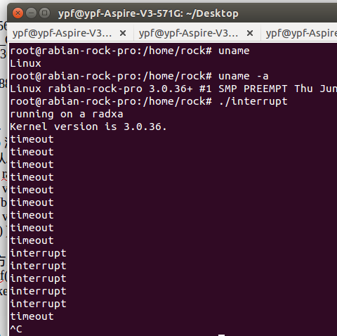
It will cause interrupt when rising edge inputs to pin 1. The result:
It should take note that, for a linux kernel version below 3.12, interrupt only support INT_EDGE_RISING or INT_EDGE_FALLING, not for INT_EDGE_BOTH.


