RockpiS/hardware/rockpiS
ROCK Pi S > Hardware > Main Board
This hardware user manual provides information about the features and signals available on ROCK Pi S board.
Hardware version
ROCK Pi S board comes with different versions. When you get the board, you need to know the hardware version like 'ROCK PI S V12', which is printed in the top side of the board.
Also, you need to know the ROCK Pi S Models and SKU, like 'ROCK Pi S D4WPN8'.
Power supply
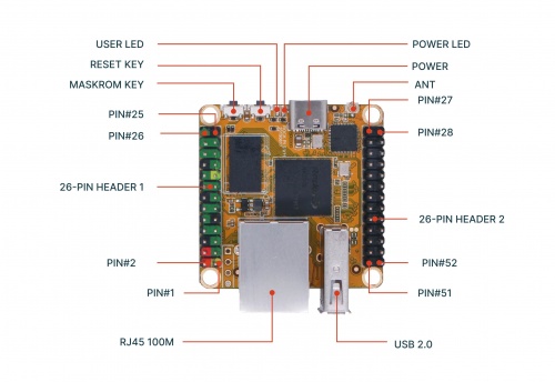
ROCK Pi S uses the USB Type-C port for both power and communication.
If you want to power ROCK Pi S standalone, you can use 5V/1A or 5V/2A power adapter with USB Type-C ports. You can also use the USB PD/QC power adapter without worrying damage the board because the PD/QC adapter will detect ROCK Pi S only supports 5V so the adapter will output 5V.
The ROCK Pi S can be powered from the PC/Laptop USB ports directly. If you also need ROCK Pi S to communicate with Host PC, you just need a USB type C to type A cable.
When you use PoE function provided by ROCK Pi S, you may power ROCK Pi S by putting DV +5V directly to PIN#2 of 26-PIN HEADER 1. GND pin like PIN#6 is also need.
Processor
The Rockchip RK3308 Soc used in ROCK Pi S RK3308 is a high-performance Quad-core application processor designed for intelligent voice interaction, audio input/output processing, and other digital multimedia applications. Embedded rich audio interfaces, such as I2S, PCM, TDM, PDM, SPDIF, HDMI ARC and so on, can meet different audio application development, reduce hardware development complexity and development cost.
- Quad-core ARM Cortex-A35CPU
- Full implementation of the ARM architecture v8-A instruction set
- ARM Neon Advanced SIMD (single instruction, multiple data) support for accelerated media and signal processing computation
- ARMv8 Cryptography Extensions
- In-order pipeline with symmetric dual-issue of most instructions
- 256KB unified system L2 cache
- Include VFP v3 hardware to support single and double-precision operations
- Integrated 32KB L1 instruction cache, 32KB L1 data cache with 4-way set associative
- TrustZone technology support
Keys
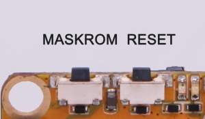
The ROCK Pi S Board presents two keys, Reset key and Maskrom key.
The Reset key serves as the hardware reset button. Short press the button to reboot the system.
The Maskrom key is for firmware flash/upgrade.
LED
ROCK Pi S has Power LED and User LED.
- Power LED
Power LED is green, which can be configured by sysfs.
The related directory is /sys/class/leds/rockpis:green:power
It is always on when ROCK Pi S is given power by default,
- User LED
User LED is blue, which can be configured by sysfs.
The related directory is /sys/class/leds/rockpis:blue:user
By default, its blink status shows the running kernel.
Networking
Ethernet
ROCK Pi S has 10/100M Bit Ethernet port.
Two LEDs are built into the RJ-45 LAN connector. This table describes the LED states when the board is powered up and the LAN subsystem is operating.
| LED | LED Color | Led State | Condition |
|---|---|---|---|
| Link | Green | Off On |
LAN link is not established. LAN link is established. |
| Data Rate | Yellow | Blinking Off |
There is activity on this port. No link is established. |
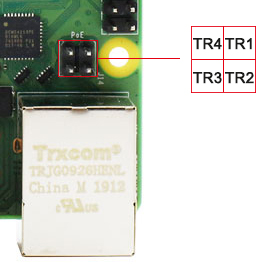
PoE
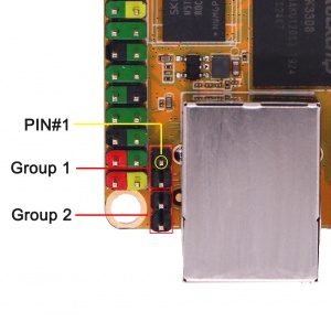
PoE connector is divided into two groups, Group 1 (PIN#1 and PIN#2) and Group2 (PIN#3 and PIN#4) .
10/100 RJ45 PoE connector pinout table.
| ROCK Pi S PoE | --- | Raspberry Pi 4B PoE |
|---|---|---|
| TR1(PIN#1) | --- | TR1 |
| TR2(PIN#2) | --- | TR2 |
| TR3(PIN#3) | --- | TR3 |
| TR4(PIN#4) | --- | TR4 |
ROCK Pi S PoE look:
Raspberry Pi 4B PoE look:
WiFi
ROCK Pi S is equipped with RTL8723DS chip, 2.4GHz 802.11 b/g/n/i/e WIFI and BT 4.0.
To gain a stronger signal, you need an antenna attached to the antenna socket on board.
SD Nand
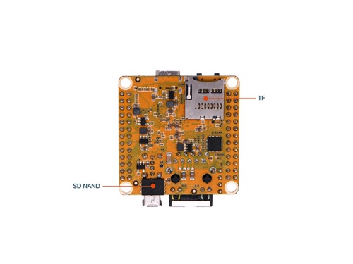
Check SD NAND for more details.
TF card/Micro SD
TF Card Interface
The TF card can be used as a system storage or an external storage. When it's used as a system storage, you'd better choose the ones with storage space larger than 8GB. When it's used as an external storage, you can choose the ones with storage space up to 128GB. When the TF card is inserted into the TF card slot, the device will be automatically recognized by the system.
The TF card interface pin specification shows below.
| Pin# | Name |
|---|---|
| 1 | SDMMC0_D2 |
| 2 | SDMMC0_D3 |
| 3 | SDMMC0_CMD |
| 4 | VCC3V3_SYS |
| 5 | SDMMC0_CLK |
| 6 | GND |
| 7 | SDMMC0_D0 |
| 8 | SDMMC0_D1 |
| 9 | SDMMC0_DET_L |
| 10 | GND |
| 11 | GND |
| 12 | GND |
| 13 | GND |
USB
USB 2.0 Type-A
USB 2.0 Type-A enables the attachment of peripherals such U Disk, keyboards, mice, USB dongle like USB camera, etc. By default, the USB port power supply is limited to 1.44A current if the system power input is enough.
USB Type-C with OTG function
USB Type-C port support On-The-Go (OTG), which means that ROCK Pi S i recognized as an device. Thus USB gadget function including adb, USB RNDIS and so on are supported by software configuration.
General purpose input-output (GPIO) connector
ROCK Pi S has two 26-pin expansion header. Each pin is distinguished by color.
For more details, see the GPIO page.

