Difference between revisions of "Rockpi4/hardware/spi flash"
(→Solder manually) |
m (fix typo) |
||
| Line 10: | Line 10: | ||
* The SPI is also exported on the 40PIN GPIO header, if we use it as boot rom, then we will not able to use the SPI bus on the GPIO header | * The SPI is also exported on the 40PIN GPIO header, if we use it as boot rom, then we will not able to use the SPI bus on the GPIO header | ||
| − | * If the bootloader in the SPI flash corrupted, it will ''brick'' the ROCK Pi 4, which is | + | * If the bootloader in the SPI flash corrupted, it will ''brick'' the ROCK Pi 4, which is hard for normal user to recover. |
* The bootloader doesn't support booting from USB3 or NVMe before and there are tools missing to write to SPI flash easily. | * The bootloader doesn't support booting from USB3 or NVMe before and there are tools missing to write to SPI flash easily. | ||
Latest revision as of 15:42, 21 June 2022
ROCK Pi 4 > Hardware > SPI Flash
Introduction
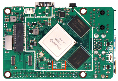
RK3399 can boot from SPI/SD card/eMMC, the SPI buses for booting is SPI1. On ROCK Pi 4 V1.3 and earlier, the design has included the SPI flash but it was not soldered. There are several reasons:
- The SPI is also exported on the 40PIN GPIO header, if we use it as boot rom, then we will not able to use the SPI bus on the GPIO header
- If the bootloader in the SPI flash corrupted, it will brick the ROCK Pi 4, which is hard for normal user to recover.
- The bootloader doesn't support booting from USB3 or NVMe before and there are tools missing to write to SPI flash easily.
Solder manually
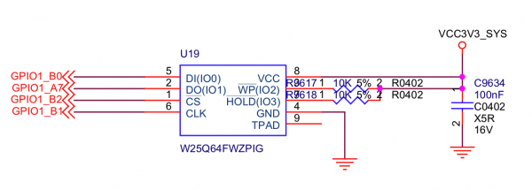
Some advanced users may want to solder the SPI flash by themself. The footprint for the SPI flash is SOP8, the voltage level is 3.3V. The size should be larger than 4MB(32Mbit) to store the bootloader. The verified working models are:
- W25Q64FV
- GD25Q127CSIG
- XT25F32B
- XT25F128B


