Difference between revisions of "RockpiX/bios"
(Created page with "{{RockpiX_header}} {{Languages|rockpiX/bios}} ROCK Pi X > BIOS == Introduction == == Check Version == == BIOS Update == ==...") |
RadxaYuntian (Talk | contribs) m (Reduce pic size) |
||
| (9 intermediate revisions by 5 users not shown) | |||
| Line 5: | Line 5: | ||
[[rockpiX | ROCK Pi X]] > [[rockpiX/bios | BIOS]] | [[rockpiX | ROCK Pi X]] > [[rockpiX/bios | BIOS]] | ||
| − | == Introduction == | + | === Introduction === |
| + | The ROCK Pi X BIOS is based on the AMI(American Megatrends, Inc) AptioV BIOS with UEFI and 64bit OS support, providing a user friendly interfaces to manage the OS booting/installing and it has a built in UEFI shell, which is convenient for developers to debug. | ||
| + | === Check version === | ||
| + | 1. Power on ROCK Pi X, keep pressing the del button on the keyboard until it enters the BIOS. | ||
| + | 2. After entering the BIOS, use the left and right arrow keys to switch to the '''"Main"''' interface. | ||
| + | [[File:Bios_main_interface.png | 600px]] | ||
| + | Check the version of '''"Build Data and Time"'''. | ||
| + | === Check eMMC === | ||
| + | For V1.3 and earlier hardware, the eMMC is pluggable, you can check if the eMMC is installed well in the BIOS menu: | ||
| − | + | Go to Chipset -> South Bridge -> LPSS & SCC Configuration to check if eMMC is detected. | |
| − | + | [[File:Bios_emmc.png|500px]] | |
| + | === UEFI Shell === | ||
| + | The UEFI Shell is a shell/terminal for the firmware which allows launching EFI applications which include UEFI bootloaders. Apart from that, the shell can also be used to obtain various other information about the system or the firmware like memory map (memmap), modifying boot manager variables (bcfg), running partitioning programs (diskpart), loading UEFI drivers, editing text files (edit), hexedit etc. | ||
| + | The UEFI Shell can be accessed by Serial Console or HDMI Display. | ||
| − | == BIOS Changelog== | + | ==== Common Used Command ==== |
| + | |||
| + | exit | ||
| + | |||
| + | If you go to the UEFI Shell by accident, you can type exit to go back to BIOS interface. | ||
| + | |||
| + | map | ||
| + | |||
| + | Check the disk mapping for the available storage, you can use it to detect if the eMMC or the USB driver is detected by BIOS. | ||
| + | |||
| + | fs0: | ||
| + | ls | ||
| + | |||
| + | Change current disk to the first disk scanned and list the content, FAT and NTFS file system are supported. | ||
| + | |||
| + | === BIOS Update === | ||
| + | |||
| + | Check [[RockpiX/bios/update]] | ||
| + | |||
| + | === Serial Access === | ||
| + | |||
| + | BIOS interface can be accessed from serial console on ROCK Pi X. Check [[RockpiX/bios/serial_console]] | ||
| + | |||
| + | === BIOS Changelog=== | ||
| + | ====V12_X64_20200924==== | ||
| + | * Modify baseboard name | ||
| + | |||
| + | ====V12_X64_20200821==== | ||
| + | * Fix the cold reset can not find ethernet phy issue | ||
| + | |||
| + | ====V12_X64_20200726==== | ||
| + | * The first release version of bios for massive production, with everything working | ||
| + | * This the default bios version shipping in the ROCK Pi X v1.3 hardware | ||
| + | |||
| + | === Recover BIOS with CH341a Programmer === | ||
| + | |||
| + | If you accidentally flash a bad BIOS image or set BIOS values which prevent your Rock Pi X from POST-ing, you can flash a BIOS image out-of-band with an affordable CH341a programmer and SOIC8 clamp (available from online retailers such as Amazon [https://www.amazon.com/D-FLIFE-CH341A-Programmer-Adapter-Converter/dp/B07YFPJQ5W] for for ~$10-15 USD). The Rock Pi X uses a 1.8V SPI flash ROM from Winbond, so make sure you get a 1.8V adapter with your CH341a programmer. | ||
| + | |||
| + | 1. Hook up the CH341a programmer to a PC using a SOIC8 clamp. Pay attention to orientation of pin 1 (silk-screened on board and/or the red color on the ribbon cable). It you have a multi-meter, it would be worth your time to test voltage of the pin 8 (VCC) -- diagonally across from pin 1 -- to a common ground. It should be ~1.8V and no more than +/- 0.1V or you risk damaging the flash ROM package. | ||
| + | |||
| + | 2. Attach the SOIC8 clamp to the Winbond SPI flash ROM package. If you look closely at the package, there will be a dot in one corner; that is pin 1, and where you clamp on the red colored cable. | ||
| + | |||
| + | [[File:Ch341a_step1.jpg]] [[File:Ch341a_step2.jpg]] | ||
| + | |||
| + | Make sure that the clip is attached correctly: | ||
| + | |||
| + | [[File:incorrect_soic8.png|300px]] [[File:correct_soic8.png|300px]] | ||
| + | |||
| + | 3. Use a SPI flash utility to write the unzip'd BIOS image (.bin file) of your choosing. On a Linux host, this can be done by building this [https://github.com/gschorcht/spi-ch341-usb] kernel module from Github and running: | ||
| + | |||
| + | sudo flashrom --programmer ch341a_spi -w ROCKPI_V12_X64_20200821.bin | ||
| + | |||
| + | The flash operation will take about a minute, after which point you can disconnect the SOIC8 clamp or CH341a from a power source and boot up your Rock Pi X. | ||
| + | |||
| + | === Recover BIOS with DEBUG port === | ||
| + | |||
| + | SPI flash can also be accessed by the onboard DEBUG port, located next to SPI flash chip. A FPC 10 pin 0.5mm pitch adapter is required: | ||
| + | |||
| + | [[File:FPC_Adapter.jpg|300px]] | ||
| + | |||
| + | Given the above adapter, the pin numbers and their functions can be found in the table below: | ||
| + | |||
| + | {| class="wikitable" | ||
| + | |'''CLK''' | ||
| + | |2 | ||
| + | |1 | ||
| + | |NC | ||
| + | |- | ||
| + | |'''DO''' | ||
| + | |4 | ||
| + | |3 | ||
| + | |'''DI''' | ||
| + | |- | ||
| + | |'''GND''' | ||
| + | |6 | ||
| + | |5 | ||
| + | |'''CS''' | ||
| + | |- | ||
| + | |NC | ||
| + | |8 | ||
| + | |7 | ||
| + | |NC | ||
| + | |- | ||
| + | |NC | ||
| + | |10 | ||
| + | |9 | ||
| + | |'''VCC''' | ||
| + | |} | ||
| + | |||
| + | You can then connect your SPI flasher to the adapter board via jumper cable instead of clamp. | ||
Latest revision as of 11:15, 23 December 2021
ROCK Pi X > BIOS
Contents
Introduction
The ROCK Pi X BIOS is based on the AMI(American Megatrends, Inc) AptioV BIOS with UEFI and 64bit OS support, providing a user friendly interfaces to manage the OS booting/installing and it has a built in UEFI shell, which is convenient for developers to debug.
Check version
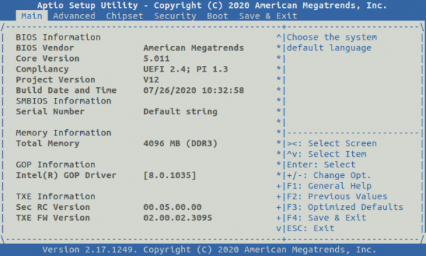
1. Power on ROCK Pi X, keep pressing the del button on the keyboard until it enters the BIOS.
2. After entering the BIOS, use the left and right arrow keys to switch to the "Main" interface.
Check the version of "Build Data and Time".
Check eMMC
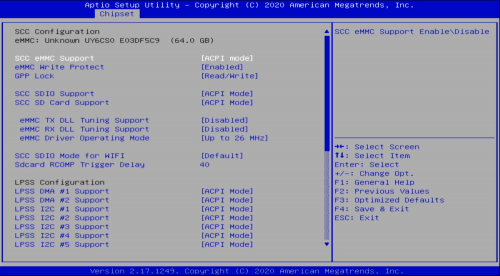
For V1.3 and earlier hardware, the eMMC is pluggable, you can check if the eMMC is installed well in the BIOS menu:
Go to Chipset -> South Bridge -> LPSS & SCC Configuration to check if eMMC is detected.
UEFI Shell
The UEFI Shell is a shell/terminal for the firmware which allows launching EFI applications which include UEFI bootloaders. Apart from that, the shell can also be used to obtain various other information about the system or the firmware like memory map (memmap), modifying boot manager variables (bcfg), running partitioning programs (diskpart), loading UEFI drivers, editing text files (edit), hexedit etc.
The UEFI Shell can be accessed by Serial Console or HDMI Display.
Common Used Command
exit
If you go to the UEFI Shell by accident, you can type exit to go back to BIOS interface.
map
Check the disk mapping for the available storage, you can use it to detect if the eMMC or the USB driver is detected by BIOS.
   fs0:
   ls
Change current disk to the first disk scanned and list the content, FAT and NTFS file system are supported.
BIOS Update
Check RockpiX/bios/update
Serial Access
BIOS interface can be accessed from serial console on ROCK Pi X. Check RockpiX/bios/serial_console
BIOS Changelog
V12_X64_20200924
- Modify baseboard name
V12_X64_20200821
- Fix the cold reset can not find ethernet phy issue
V12_X64_20200726
- The first release version of bios for massive production, with everything working
- This the default bios version shipping in the ROCK Pi X v1.3 hardware
Recover BIOS with CH341a Programmer
If you accidentally flash a bad BIOS image or set BIOS values which prevent your Rock Pi X from POST-ing, you can flash a BIOS image out-of-band with an affordable CH341a programmer and SOIC8 clamp (available from online retailers such as Amazon [1] for for ~$10-15 USD). The Rock Pi X uses a 1.8V SPI flash ROM from Winbond, so make sure you get a 1.8V adapter with your CH341a programmer.
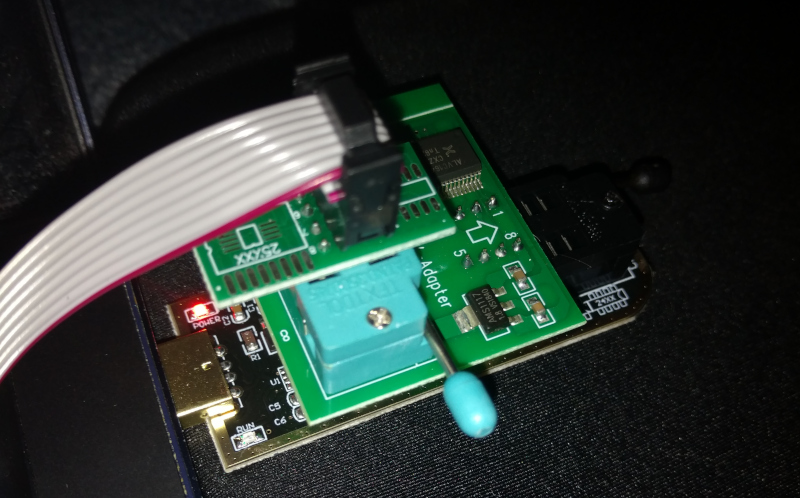
1. Hook up the CH341a programmer to a PC using a SOIC8 clamp. Pay attention to orientation of pin 1 (silk-screened on board and/or the red color on the ribbon cable). It you have a multi-meter, it would be worth your time to test voltage of the pin 8 (VCC) -- diagonally across from pin 1 -- to a common ground. It should be ~1.8V and no more than +/- 0.1V or you risk damaging the flash ROM package.
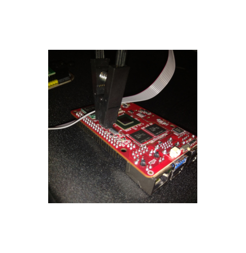
2. Attach the SOIC8 clamp to the Winbond SPI flash ROM package. If you look closely at the package, there will be a dot in one corner; that is pin 1, and where you clamp on the red colored cable.
Make sure that the clip is attached correctly:
3. Use a SPI flash utility to write the unzip'd BIOS image (.bin file) of your choosing. On a Linux host, this can be done by building this [2] kernel module from Github and running:
sudo flashrom --programmer ch341a_spi -w ROCKPI_V12_X64_20200821.bin
The flash operation will take about a minute, after which point you can disconnect the SOIC8 clamp or CH341a from a power source and boot up your Rock Pi X.
Recover BIOS with DEBUG port
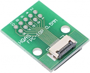
SPI flash can also be accessed by the onboard DEBUG port, located next to SPI flash chip. A FPC 10 pin 0.5mm pitch adapter is required:
Given the above adapter, the pin numbers and their functions can be found in the table below:
| CLK | 2 | 1 | NC |
| DO | 4 | 3 | DI |
| GND | 6 | 5 | CS |
| NC | 8 | 7 | NC |
| NC | 10 | 9 | VCC |
You can then connect your SPI flasher to the adapter board via jumper cable instead of clamp.

