Difference between revisions of "Rock3/CM3/raspcm4io"
(→Boot the board to maskrom mode) |
(→Boot the board to maskrom mode) |
||
| Line 122: | Line 122: | ||
* 3.Press the key and hold, short the follow pins, and then disconnect the pins,release the key. | * 3.Press the key and hold, short the follow pins, and then disconnect the pins,release the key. | ||
| − | [[File: | + | [[File:Cm4-io-maskrom.jpg |400px]] |
* 4. For Linux/macOS | * 4. For Linux/macOS | ||
Revision as of 12:22, 13 October 2021
ROCK 3 > Compute Module 3 > Raspberry Pi CM4 IO Board
Contents
[hide]Getting Started
What you need
Necessary
- CM4 IO main board
- CM4 IO top board
- One of the Storage media below:
- microSD, larger than 8GB.
- Power supply
- The CM4 is powered by DC port and has a wide range of input voltage, 12V.
- USB Keyboard and Mouse
- With four USB-A connectors, CM4 IO can be equipped with a full sized keyboard and mouse.
- Monitor and HDMI Cable
- CM4 IO is equipped with a full sized HDMI connector. HDMI capable monitor is recommended.
- HDMI EDID display data is used to determine the best display resolution. On monitors and TVs that support 1080p (or 4K) this resolution will be selected. If 1080p is not supported the next available resolution reported by EDID will be used. This selected mode will work with MOST but not all monitors/TVs.
- Micro USB
- If you want write image on CM4 IO from USB port , commands you need an USB Male A to Micro USB cable to connect CM4 IO and PC.
Optional
- microSD Card Reader
- For flashing the image into microSD Card
- USB type A to type Micro USB
- Write image on CM4 IO from USB port
- USB to TTL serial cable
- This is needed for serial console.
- Ethernet cable
- CM4 IO supports Internet access via WIFI or Ethernet.
- An Ethernet cable is used to connect your CM4 IO to a local network and the Interne
- Audio cable
- Audio can be played through speaker or headphones using a standard 3.5mm jack.
- WiFi/BT Cards
Install on eMMC from USB port
CM4 supports Maskrom mode, which is a special operation mode for CPU to wait for Micro USB port command. The PC tools we use to communicate with CM4 IO in Maskrom mode are the rkdevelopment tool and AndroidTool tool. We use the rkdevelopment tool in Linux/macOS and the AndroidTool tool under Windows.
Requirement
- CM4 IO board
- Power adapter
- USB Male A to Micro USB .
Install Tools&Drivers
Windows
Step 1:Install Android tool
The tool is provided in a compressed package. First, download the compressed package of this tool, and click the download link (RKDevTool_Release_v2.81.zip). After downloading, unzip it. Installation is complete.
Step 2:Install driver
Using the RK driver assistant tool to install the driver.
There’s no need to connect your Rockchip device during this procedure just download and extract RKDriverAssistant.zip
Then double click on DriverInstall.exe in the RKDriverAssistant directory to start the utility. If you installed the Rockchip USB drivers for any other Rockchip devices already, make sure you click “Uninstall Driver” first.
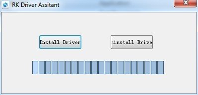
Then click “Install Driver”, the driver has finish installing.
Linux
For Linux, we build the rkdeveloptool, >=1.32, from source code. To build rkdeveloptool on a Debian based Linux distribution, follow the instruction below: Install build dependency:
sudo apt-get install libudev-dev libusb-1.0-0-dev dh-autoreconf
Clone the source code and build:
 git clone https://github.com/rockchip-linux/rkdeveloptool
 cd rkdeveloptool
 autoreconf -i
 ./configure
 make
If you encounter compile error like below
   ./configure: line 4269: syntax error near unexpected token `LIBUSB1,libusb-1.0'
   ./configure: line 4269: `PKG_CHECK_MODULES(LIBUSB1,libusb-1.0)'
You should install pkg-config libusb-1.0
sudo apt-get install pkg-config libusb-1.0
Then re-run
   autoreconf -i
   ./configure
   make
Now you have rkdeveloptool executable at the current directory.
sudo cp rkdeveloptool /usr/local/bin/
MacOS
Boot the board to maskrom mode
To boot CM4 IO into maskrom mode is simple:
- 1. Power off the board
- remove microSD card
- 2. Plug the USB Male A to Micro USB cable to CM4 IO port(the upper USB3 port), the other side to PC
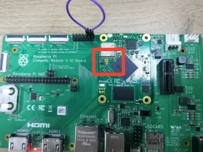
- 3.Press the key and hold, short the follow pins, and then disconnect the pins,release the key.
- 4. For Linux/macOS
Now on your Linux PC, lsusb command show show the following usb devices
Bus 003 Device 005: ID 2207:330c
- 5. For Windows
Open device manager in your Windows PC, check the Device Manager:
It means the device is in maskrom mode now.
- 6. Now plug the eMMC module and proceed the next step to flash.
Alternatively, if you are running Android and can access ADB, you can reboot the device to loader mode `adb reboot bootloader` then use the rkdeveloptool to reset the device into maskrom mode `rkdeveloptool rd 3` or Windows AndroidTool Switch button to go to maskrom mode.
Begin Installation USB -> eMMC
Linux/macOS
On your PC, run the rkdeveloptool
   rkdeveloptool ld        # List the device
   DevNo=1	Vid=0x2207,Pid=0x330c,LocationID=305	Maskrom
Download the loader (flash helper) to init the ram and prepare the flashing environment etc. If you don't have it, you can download it from here
rkdeveloptool db rk356x_loader_vxxxx.bin
Write the GPT image to eMMC, start to write from offset 0. you can get image from here.
rkdeveloptool wl 0 /path/to/xxx-gpt.img
Reboot the device
rkdeveloptool rd
Now the device should boot the new image on eMMC
Please notice that when you want to erase eMMC on board, you can use this command. Get zero.img from here.
   rkdeveloptool db rk356x_loader_vxxxx.bin
   rkdeveloptool wl 0 zero.img
Windows
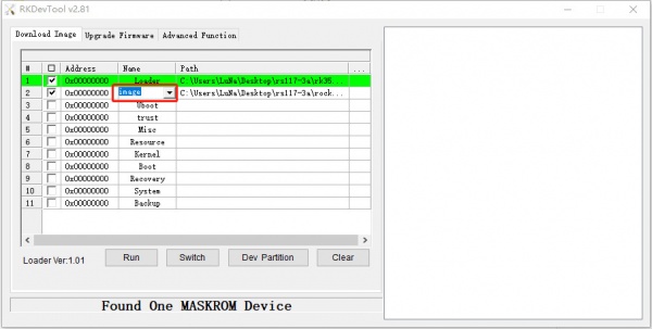
Double click the RKDevTool.exe and you will see the following interface:
Double click this red box and modify it to image in the second row.
Step 1: Select Loader
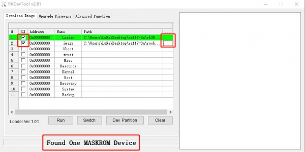
If your CM4 IO is in maskrom mode and connects to PC, you can see that the program detect it Found one MASKROM Device in the red box
Next, click the button in the first row on the right last columns select the loader "rk356x_xxx_ loader_ xxxxx.bin ",
Note: the loader (flash helper) is used to init the ram and prepare the flashing environment etc. If you don't have it, you can download it from here
Step 2: Select Image
Then click the right last columns to in the Image row and choose the image you want to flash.You can download the image from here
Note: Normally the image name should ends with xxx-gpt.img. If the image name ends with xxx-rkupdate.img, you can not flash with this method.
Step 3: Run
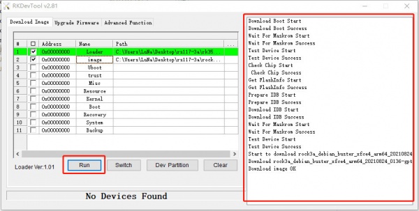
Finally, click the "run" button, and you will see the content on the right. When the progress reaches 100% or show Download image OK in the red box, the download is completed.
Status
Resource
General purpose input-output (GPIO) connector
CM4 IO has a 40-pin expansion header. Each pin is distinguished by color.
| GPIO number | Function4 | Function3 | Function2 | Function1 | Pin# | Pin# | Function1 | Function2 | Function3 | Function4 | GPIO number | |
|---|---|---|---|---|---|---|---|---|---|---|---|---|
| +3.3V | 1 | 2 | +5.0V | |||||||||
| 14 | SPI0_MOSI_M0 | I2C2_SDA_M0 | PWM2_M1 | GPIO0_B6 | 3 | 4 | +5.0V | |||||
| 13 | SPI0_CLK_M0 | I2C2_SCL_M0 | PWM1_M1 | GPIO0_B5 | 5 | 6 | GND | |||||
| 125 | I2S1_SDI3_M1 | SDMMC2_PWREN_M0 | GPIO3_D5 | 7 | 8 | GPIO0_D1 | UART2_TX_M0 | 25 | ||||
| GND | 9 | 10 | GPIO0_D0 | UART2_RX_M0 | 24 | |||||||
| 23 | UART0_CTSn | PWM0_M1 | GPIO0_C7 | 11 | 12 | GPIO3_C7 | I2S1_SCLK_TX_M1 | 119 | ||||
| 15 | PWM0_M0 | GPIO0_B7 | 13 | 14 | GND | |||||||
| 19 | PWM4 | VOP_PWM_M0 | GPIO0_C3 | 15 | 16 | GPIO3_D4 | I2S1_SDI2_M1 | 124 | ||||
| +3.3V | 17 | 18 | GPIO3_D3 | I2S1_SDI1_M1 | 123 | |||||||
| 138 | I2S2_SDI_M1 | SPI3_MOSI_M0 | I2C4_SDA_M0 | GPIO4_B2 | 19 | 20 | GND | |||||
| 136 | SPI3_MISO_M0 | I2S1_SDO1_M1 | GPIO4_B0 | 21 | 22 | GPIO3_C6 | I2S1_MCLK_M1 | 118 | ||||
| 139 | I2S2_SDO_M1 | SPI3_CLK_M0 | I2C4_SCL_M0 | GPIO4_B3 | 23 | 24 | GPIO4_A6 | I2S1_SCLK_RX_M1 | SPI3_CS0_M0 | 134 | ||
| GND | 25 | 26 | SARADC_IN3 | |||||||||
| 140 | I2C2_SDA_M1 | GPIO4_B4 | 27 | 28 | GPIO4_B5 | I2S1_SDO3_M1 | I2C2_SCL_M1 | 141 | ||||
| 137 | I2S1_SDO2_M1 | ISP_PRELIGHT_TRIG | GPIO4_B1 | 29 | 30 | GND | ||||||
| 21 | SPI0_MISO_M0 | PWM6 | GPIO0_C5 | 31 | 32 | GPIO4_C0 | PWM11_IR_M1 | 144 | ||||
| 22 | SPI0_CS0_M0 | PWM7_IR | GPIO0_C6 | 33 | 34 | GND | ||||||
| 120 | I2S1_LRCK_TX_M1 | GPIO3_D0 | 35 | 36 | GPIO4_A7 | I2S1_LRCK_RX_M1 | SPI3_CS1_M0 | 135 | ||||
| 18 | PWM3_IR | GPIO0_C2 | 37 | 38 | GPIO3_D2 | I2S1_SDI0_M1 | 122 | |||||
| GND | 39 | 40 | GPIO3_D1 | I2S1_SDO0_M1 | 121 |
More details about 40-pin Header
- Pins marked with color orange are designed for debug console.
- PWM:x7,PWM0/PWM1/PWM2/PWM3/PWM6/PWM7/PWM11
- SPI:X2,SPI0/SPI3
- I2C:X2,I2C2/I2C4
- UART:X2,UART0/UART2
- ADC:X1, SARADC_IN3
- I2S:X2, I2S1/I2S2
IO Voltage
RK3566 have three IO voltages, 1.8V/3.3V. For CM4 IO, the high level voltage of GPIO pin on 40-PIN HEADER is 3.3V.
| GPIO       | Voltage Level | Tolerance |
| ---------- | ------------- | --------- |
| SARADC_IN3    | 1.8V          | 1.98V     |
GPIO number
Rockchip RK3566 GPIO has 5 banks, GPIO0 to GPIO4, each bank has 32pins, naming as below:
GPIO0_A0 ~ A7
GPIO0_B0 ~ B7
GPIO0_C0 ~ C7
GPIO0_D0 ~ D7

GPIO1_A0 ~ A7
....
GPIO1_D0 ~ D7
The GPIO number can be calculated as below, take GPIO4_D1 (PIN26 on 4-0PIN HEADER) as an example:
GPIO4_D1 = 4*32 + 3*8 + 1 = 153
(A=0, B=1, C=2, D=3)
To set GPIO4_D1 output
cd /sys/class/gpio
echo 153 > export
cd gpio153
echo out > direction
echo 1 > value     # output high
echo 0 > value     # output low

