Difference between revisions of "Rock5/hardware/5b"
(→Recovery Button (21)) |
|||
| (2 intermediate revisions by one other user not shown) | |||
| Line 5: | Line 5: | ||
[[rock5 | ROCK 5]] > [[rock5/hardware | Hardware]] > [[Rock5/hardware/5b | ROCK 5B Hardware Details]] | [[rock5 | ROCK 5]] > [[rock5/hardware | Hardware]] > [[Rock5/hardware/5b | ROCK 5B Hardware Details]] | ||
| + | |||
| + | =====[https://docs.radxa.com/en/rock5/rock5b/hardware-design/hardware-interface The latest hardware info of ROCK 5B is updated on the new Radxa Documentation site.]===== | ||
In this page we will provide detailed hardware information of ROCK 5B. | In this page we will provide detailed hardware information of ROCK 5B. | ||
| Line 22: | Line 24: | ||
The Radxa ROCK 5 Model B is designed to be an ARM desktop Single Board Computer with low power consumption. It supports the following power input: | The Radxa ROCK 5 Model B is designed to be an ARM desktop Single Board Computer with low power consumption. It supports the following power input: | ||
| − | * USB '''PD2.0''' power adapter which support 12V/15V/20V with 2A current or higher output | + | * USB '''PD2.0''' power adapter which support 5v with 5A current or 12V/15V/20V with 2A current or higher output |
| + | ** See [[Rock5/5b/power_supply | Power supply]] for a power supply compatibility list | ||
| + | ** Many power supply won't deliver more than 3 amps at 5v even if the wattage on other voltages are higher. | ||
* Power adapter with fixed 9V to 20V DC voltage and USB C plug | * Power adapter with fixed 9V to 20V DC voltage and USB C plug | ||
* 5V PoE power from the GPIO PIN 2 & 4 | * 5V PoE power from the GPIO PIN 2 & 4 | ||
Latest revision as of 10:10, 21 March 2024
ROCK 5 > Hardware > ROCK 5B Hardware Details
The latest hardware info of ROCK 5B is updated on the new Radxa Documentation site.
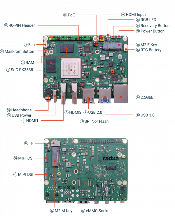
In this page we will provide detailed hardware information of ROCK 5B.
Processor (1)
The SoC powers ROCK 5B is Rockchip RK3588. The main system CPU is a Quad-core ARM Cortex-A76 MPCore processor and quad-core ARM Cortex-A55 MPCore processor, both are high-performance, low-power and cached application processor. Embedded ARM Mali-G610 MP4 3D GPU makes RK3588 completely compatible with OpenGLES 1.1, 2.0, and 3.2, OpenCL up to 2.2 and Vulkan1.2. Special 2D hardware engine with MMU will maximize display performance and provide very smoothly operation. The build-in NPU supports INT4/INT8/INT16/FP16 hybrid operation and computing power is up to 6TOPs. In addition, with its strong compatibility, network models based on a series of frameworks such as TensorFlow/MXNet/PyTorch/Caffe can be easily converted.
RAM (2)
The ram for ROCK 5B is LPDDR 4x, two 32bits LPDDR 4x chips make 64bits, data frequency is up to 4224Mhz. ROCK 5B offers 4GB, 8GB and 16GB ram size options.
USB Power (3)
The Radxa ROCK 5 Model B is designed to be an ARM desktop Single Board Computer with low power consumption. It supports the following power input:
- USB PD2.0 power adapter which support 5v with 5A current or 12V/15V/20V with 2A current or higher output
- See Power supply for a power supply compatibility list
- Many power supply won't deliver more than 3 amps at 5v even if the wattage on other voltages are higher.
- Power adapter with fixed 9V to 20V DC voltage and USB C plug
- 5V PoE power from the GPIO PIN 2 & 4
HDMI Output (4 / 5)
HDMI Input (6)
USB2.0 (7)
USB3.0 (8)
2.5GbE (9)
PoE (10)
M.2 E-KEY (11)
M.2 E Key pin signal definition table.
| Pin# | Name |
|---|---|
| 1 | GND |
| 2 | VCC3V3_WF |
| 3 | USB2_M2_DP |
| 4 | VCC3V3_WF |
| 5 | USB2_M2_DM |
| 6 | WIFI_LED |
| 7 | GND |
| 8 | PCM_CLK/I2S_SCK |
| 9 | SDIO_CLK |
| 10 | PCM_SYNC/I2S_WS |
| 11 | SDMMC2_CMD_M0 |
| 12 | PCM_OUT/I2S SD_OUT |
| 13 | SDMMC2_D0_M0 |
| 14 | PCM_IN/I2S SD_IN |
| 15 | SDMMC2_D1_M0 |
| 16 | NC |
| 17 | SDMMC2_D2_M0 |
| 18 | GND |
| 19 | SDMMC2_D3_M0 |
| 20 | BT_WAKE_HOST_H_GPIO4_B4 |
| 21 | WIFI_WAKE_HOST_H_GPIO3_D5 |
| 22 | UART1_RX_M0 |
| 23 | WIFI_REG_ON_H_GPIO3_D4 |
| 32 | UART1_TX_M0 |
| 33 | GND |
| 34 | UART1_CTS_M0 |
| 35 | PCIE_TXP |
| 36 | UART1_RTS_M0 |
| 37 | PCIE_TXN |
| 38 | NC |
| 39 | GND |
| 40 | NC |
| 41 | PCIE20_RXP |
| 42 | BT_REG_NO |
| 43 | PCIE20_RXN |
| 44 | NC |
| 45 | GND |
| 46 | NC |
| 47 | PCIE20_REFCLKP |
| 48 | NC |
| 49 | PCIE20_REFCLKN |
| 50 | WIFIBT_32KIN_1T1R |
| 51 | GND |
| 52 | PCIE_PERSTN |
| 53 | PCIE_CLKREQN |
| 54 | HOST_WAKE_BT_H |
| 55 | PCIE_WAKEN |
| 56 | BT_REG_ON_H |
| 57 | GND |
| 58 | I2C4_SDA_M1 |
| 59 | NC |
| 60 | I2C4_SCL_M1 |
| 61 | NC |
| 62 | NC |
| 63 | GND |
| 64 | NC |
| 65 | NC |
| 66 | NC |
| 67 | NC |
| 68 | NC |
| 69 | GND |
| 70 | BT_WAKE |
| 71 | NC |
| 72 | VCC3V3_WF |
| 73 | NC |
| 74 | VCC3V3_WF |
| 75 | GND |
| 76 | GND |
| 77 | GND |
| 78 | NC |
| 79 | NC |
M.2 M-KEY (12)
eMMC (13)
Socket on Board Interface Feature
The high performance eMMC module is the best choice as the system storage for ROCK 5B. The eMMC module with 8GB/16GB/32GB/64GB/128GB is available.
The eMMC Socket pin specification shows below.
| Name | Pin# | Pin# | Name | |
|---|---|---|---|---|
| GND | 1 | 34 | GND | |
| EMMC_D5 | 2 | 33 | EMMC_D6 | |
| GND | 3 | 32 | GND | |
| EMMC_D4 | 4 | 31 | EMMC_D7 | |
| GND | 5 | 30 | GND | |
| EMMC_D0 | 6 | 29 | EMMC_D1 | |
| GND | 7 | 28 | GND | |
| EMMC_CLK | 8 | 27 | EMMC_D2 | |
| GND | 9 | 26 | GND | |
| EMMC_D3 | 10 | 25 | EMMC_CMD | |
| GND | 11 | 24 | GND | |
| EMMC_RSTN | 12 | 23 | VCC3V3_SYS | |
| GND | 13 | 22 | VCC3V3_SYS | |
| GND | 14 | 21 | VCC_1V8 | |
| EMMC_RCLK | 15 | 20 | VCC_1V8 | |
| GND | 16 | 19 | GND | |
| GND | 17 | 18 | GND |
TF (14)
The TF card can be used as a system storage or an external storage.
When it's used as a system storage, you had better choose the ones with storage space larger than 8GB.
When it's used as an external storage, you can choose the ones with storage space up to 128GB.
When the TF card is inserted into the TF card slot , the device will be automatically recognized by the system.
The TF card interface pin specification shows below.
| Pin# | Name |
|---|---|
| 1 | SDMMC0_D2 |
| 2 | SDMMC0_D3 |
| 3 | SDMMC0_CMD |
| 4 | VCC3V3_SYS |
| 5 | SDMMC0_CLK |
| 6 | GND |
| 7 | SDMMC0_D0 |
| 8 | SDMMC0_D1 |
| 9 | SDMMC0_DET_L |
| 10 | GND |
| 11 | GND |
| 12 | GND |
| 13 | GND |
Headphone (15)
MIPI CSI (16)
MIPI DSI (17)
40-pin Header (18)
Please see ROCK 5B GPIO pinout.
SPI Nor Flash (19)
RTC Battery (20)
The RTC connector is designed according to the standard connector type.
You can distinguish '+3.3V' and '-' from the silk screen on the board.
| Pin# | Name |
|---|---|
| 1 | GND |
| 2 | +3.3V |
Recovery Button (21)
ROCK 5B supports loader mode, which is a special operation mode for CPU to wait for USB OTG port command.
Recovery button is used for upgrade image on SPI Nor Flash or eMMC on board.
Below is the steps of booting device into loader mode.
- Make sure that u-boot images are pre-installed on SPI Nor Flash or eMMC
- Press and hold the recovery button
- Plug the USB Male A to Male C cable to ROCK 5B Type-C port, the other side to PC
- Wait for about 5 seconds
- Confirm that ROCK 5B is in loader mode
   For macOS PC: Bus 000 Device 004: ID 2207:350b Fuzhou Rockchip Electronics Co., Ltd. USB download gadget  Serial: b021125bbff6ef30
   For Linux PC: Bus 001 Device 034: ID 2207:350b Fuzhou Rockchip Electronics Company USB download gadget
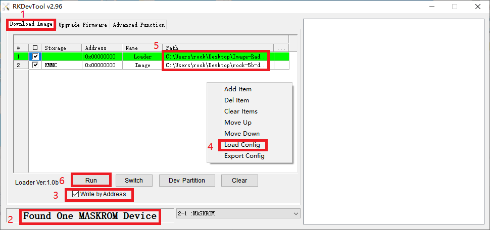
   For Windows PC: Open RKDevTool and you would see "Found One LOADER Device".
Power Button (22)
The power button is used to turn the device on or off.
Short-pressing power button would power on/off the device. This is what we called power on/off via software.
Power button also provides function of hardware power on/off the device. When the system is crashed, you can shutdown the device via this method. Press and hold the power button for at least 6 seconds. Then release the power button. After that short press power button would power on the device.
RGB LED (23)
Fan (24)
Definition table (From top to bottom in the picture)
| Pin# | Name |
|---|---|
| 1 | +5.0V |
| 2 | GND |
Maskrom Button (25)
ROCK 5B supports Maskrom mode, which is a special operation mode for CPU to wait for USB OTG port command.
Maskrom button is needed when writing the images to SPI Nor Flash or eMMC on board.
To boot ROCK 5B into maskrom mode, try the following steps.
- Press and hold the Maskrom key
- Plug the USB Male A to Male C cable to ROCK 5B Type-C port, the other side to PC
- Confirm that ROCK 5B is in Maskrom mode .
- For macOS host: lsusb result: Bus 000 Device 004: ID 2207:350b Fuzhou Rockchip Electronics Co., Ltd. Composite Device
- For Linux host: lsusb result: Bus 001 Device 030: ID 2207:350b Fuzhou Rockchip Electronics Company
- For Windows host: Open RKDevTool and you would see the device is in Found One MASKROM Device.


